Variants of variable area flowmeters
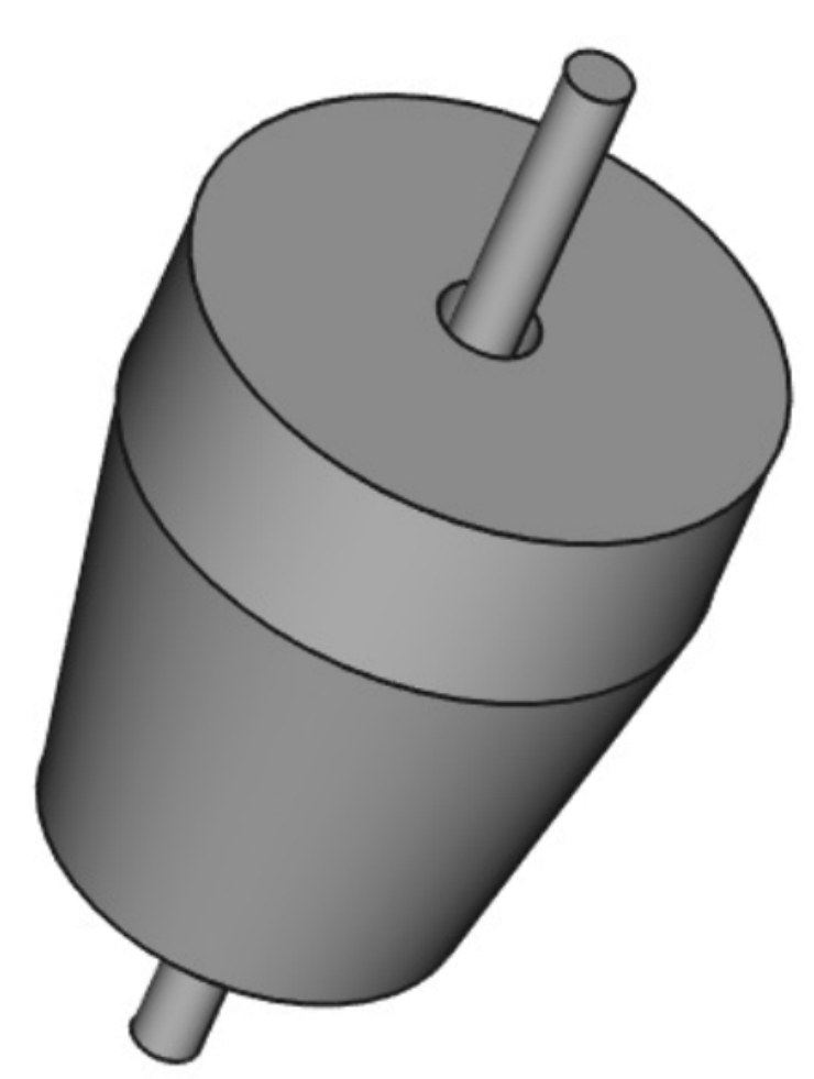
The standard variable area flowmeter consists of a conical measuring tube and a cylindrical float or ball.In addition to these traditional types, the following different designs have also proven themselves on the market.
Measuring ring / orifice plate
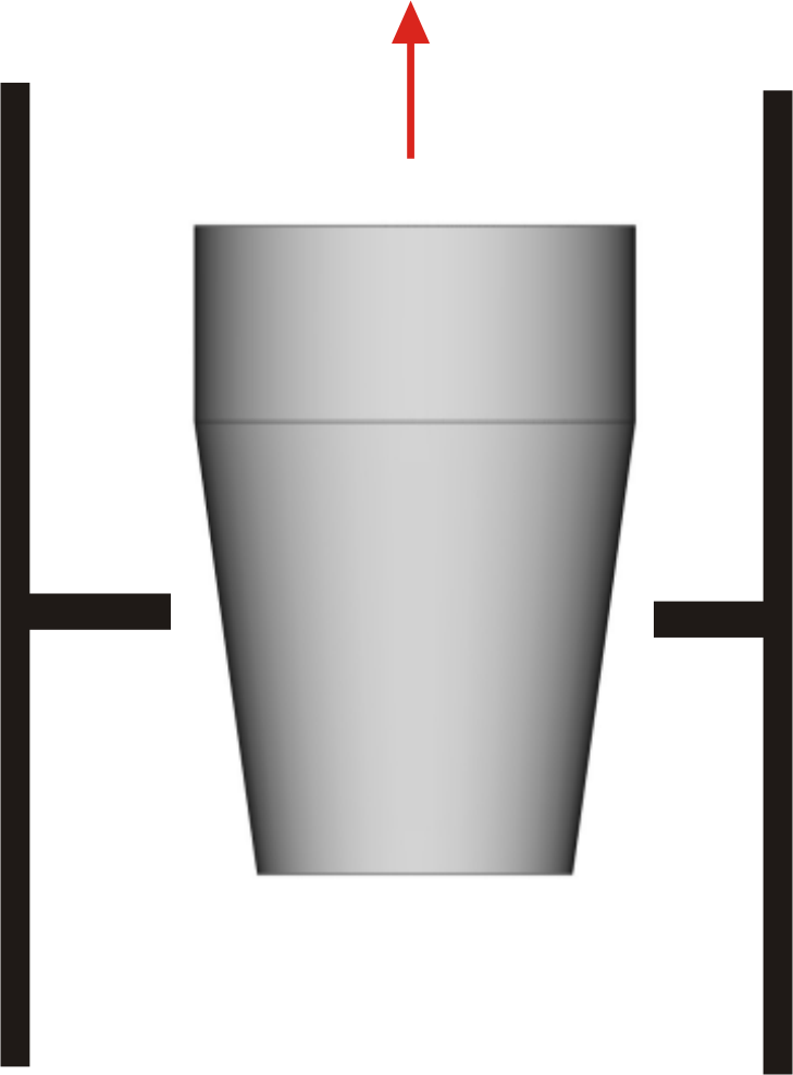
A measuring ring with a precise inner bore is installed in a cylindrical measuring tube. A conical float moves in it and hovers at a height depending on the flow. The float is held in a centric position by a guide rod or guide elements attached to the float. The position of the float is transmitted via a magnet to a display unit with scale mounted outside the measuring tube. The advantage of this design is that the time-consuming production of a conical measuring tube is no longer necessary and almost any material can be used, in which the measuring ring is mounted. An additional lining with corrosion-resistant material (PTFE etc.) enables use even with the most aggressive fluids.
Slotted nozzle
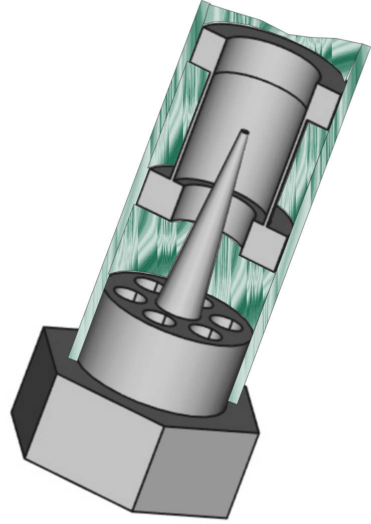
In a cylindrical metal tube with conical slots, there is a cylindrical float which floats at a certain height depending on the flow rate. For the low-pressure range (max. approx. 10 bar), the slotted nozzle is located in a glass tube with an imprinted measuring scale. For the high-pressure range (max. approx. 350 bar), the slotted nozzle is mounted in an all-metal housing. The flow rate is indicated by magnetic transmission of the float level to an indicator unit mounted on the outside of the housing. The advantage of this design is the compact construction, but this is at the expense of measuring accuracy. Because the distance between the float and the outer protective housing is always the same, the units can be easily equipped with reed contacts for monitoring the flow. The preferred application is the measurement/monitoring of cooling water in machine or plant construction.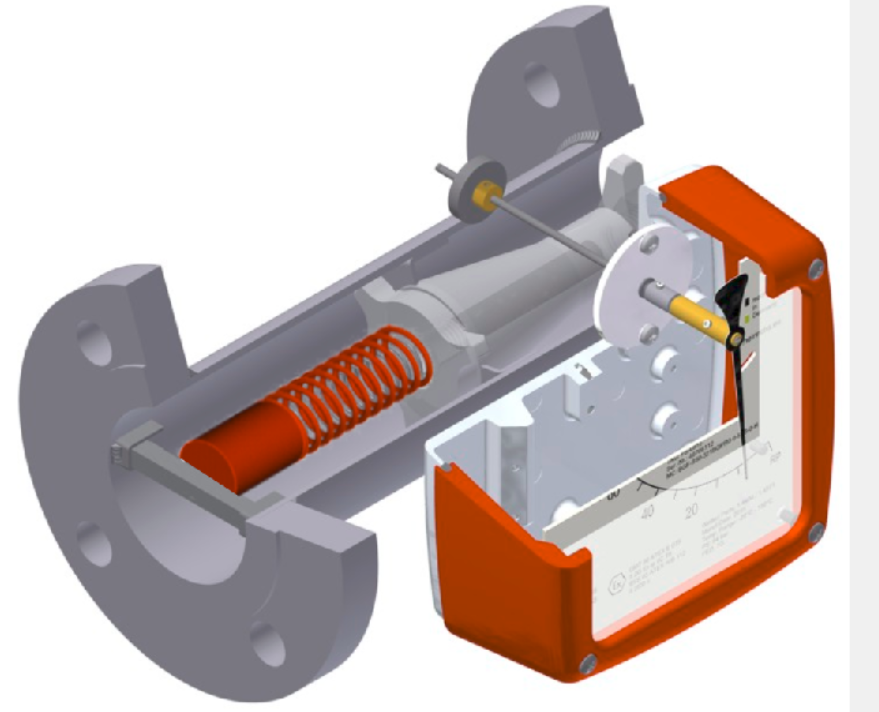
Spring-loaded
The basic version of the variable area flowmeters must be installed vertically with flow from bottom to top.By installing an additional spring as a restoring force, the devices can also be installed horizontally or from top to bottom.
This additional restoring force results in a faster response of the float when the flow rate is reduced, especially with viscous fluids.
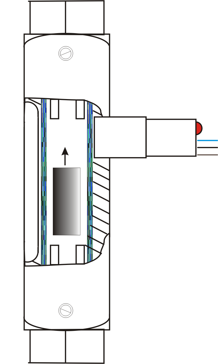
With fixed switching point
For some applications, devices are required that have a fixed, non-manipulable switching point (e.g. fuel oil identification, shielding gas for welding). For this purpose, devices are used in which a cylindrical float moves in a cylindrical glass tube. At a defined minimum flow rate, the metallic float rises up to the upper stop and switches a proximity switch mounted outside the device. The switching point is determined by the dimensions and weight of the float at the factory. Floats that switch at the lowest flow rate and still allow larger flow rates without significant pressure loss are also available.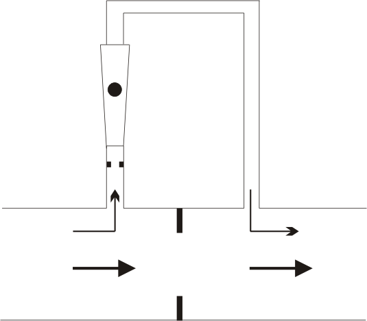
Bypass variable area flow meter
Bypass variable area flowmeters are occasionally used for larger nominal sizes. In this case, a small partial flow is diverted through an orifice plate installed in the main flow and the resulting differential pressure. DThe partial flow is passed through the variable area flow meter via a hole in the main pipe and the flow can be read on a calibrated scale.Main flow and partial flow are almost proportional by installing a small orifice upstream of the variable area flowmeter, with the same flow characteristics as the main orifice.
Orifice plate and float are normally supplied as calibrated measuring equipment.
Types of floats
A wide variety of float types are used in variable area flowmeters. This allows the measuring device to be optimally adapted to the measuring task.The diameter of the float is determined by the inner diameter of the measuring tube. It defines the annular gap between the float and the measuring tube and thus the opening through which the fluid can flow.
The weight of the float determines the force opposing the flow and the buoyancy.
Since the diameter of the float is limited by the measuring tube, the weight of the float can only be influenced by using different materials. Various metals, plastics, glass, ceramics or even hollow floats are used as materials. The chemical resistance to the fluid must be taken into account.
For accurate measurement, it is necessary that the float floats exactly centrically and that there are no friction losses due to contact with the fluid. There are various ways to ensure this.
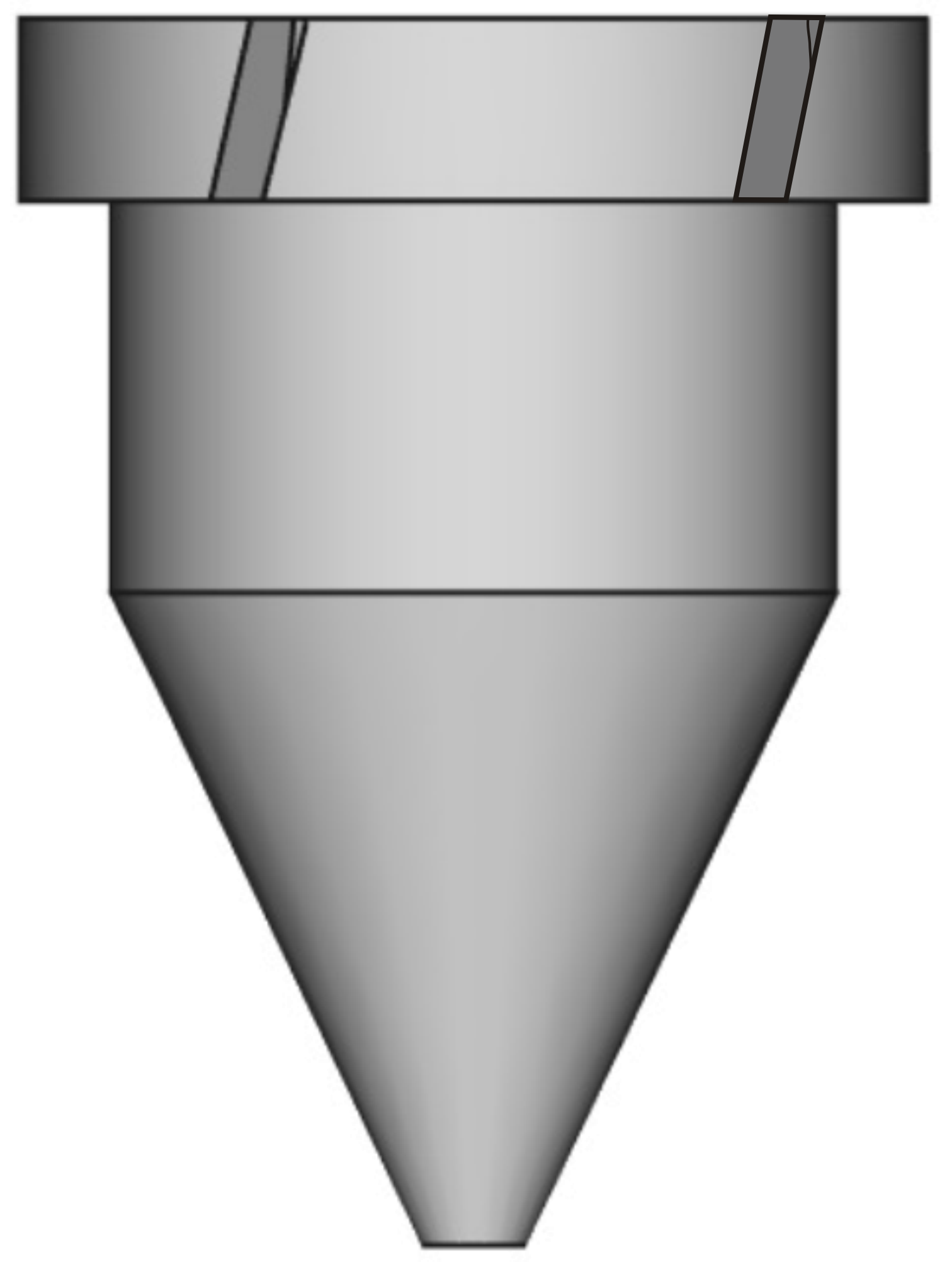
- The float is given inclined notches which cause it to rotate through the fluid (rotameter).
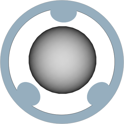
- For ball floats, 3-ribs or 3-point measuring tubes are used for centring and reducing the contact of the ball with the measuring tube wall.
- Especially with larger cylindrical floats, the float is centred by a centric guide rod or also by additional guide rings on the float.
Float shapes
Cylinder
Cylindrical floats are often used as standard floats in conical measuring tubes.
It should be noted that the shape has been fluidically optimised so that they float centrically and quietly in the middle of the measuring tube.Conical cylinder
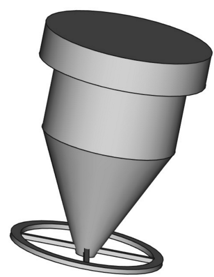
Conical floats are mainly used in cylindrical measuring tubes with a built-in orifice.
The floats are held centrally in the measuring tube with a centric guide rod or guide rings.
The level of the float is transmitted by magnets in the float to an externally mounted display scale.Ball
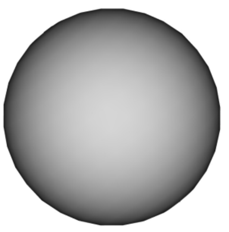
For small nominal diameters (approx. ½", DN15), balls are often used as floats.
By using a wide variety of materials (glass, plastic, metal), even the smallest flow rates can be measured accurately. The measuring tube must be transparent with a scale attached, as no transmission of the float level to an external display unit can take place.
The reference line for reading the measured value on the scale is either the upper edge or the centre of the ball.
The manufacturer's instructions must be observed.Special design
In addition to the above-mentioned float designs, there are also a large number of special designs for special measuring tasks.
ZuFor example: for gases with low pressure loss, floats that are independent of viscosity over a wide range or floats for high flow rates in small nominal diameters.

